Getting 5V Logic from the TM4C Launchpad [Repost from my UT Blog]
I am a TA for the Embedded Systems Lab Course at UT, EE 445L. In the lead-up to our final project, where students design and implement a project of their choosing, many teams decided to use 5V servo motors. While some servos may get away with 3.3V level logic, I decided to investigate how to get 5V logic from our launchpads without extra hardware. It turns out that it is fairly simple to do, since the GPIO pins on the TM4C are mostly 5V tolerant, and have Open Drain functionality. Here is a guide on how to enable this capability:
Warning: Do not follow this guide using a pin which is not 5V tolerant, on the TM4C123GH6PM, PD4, PD5, PB0 and PB1 are not 5V tolerant.
As well, ensure that you have an oscilloscope or logic analyzer that can handle 5V, to verify expected operation, as there are variances in the manufacture of all semiconductor devices.
Theory
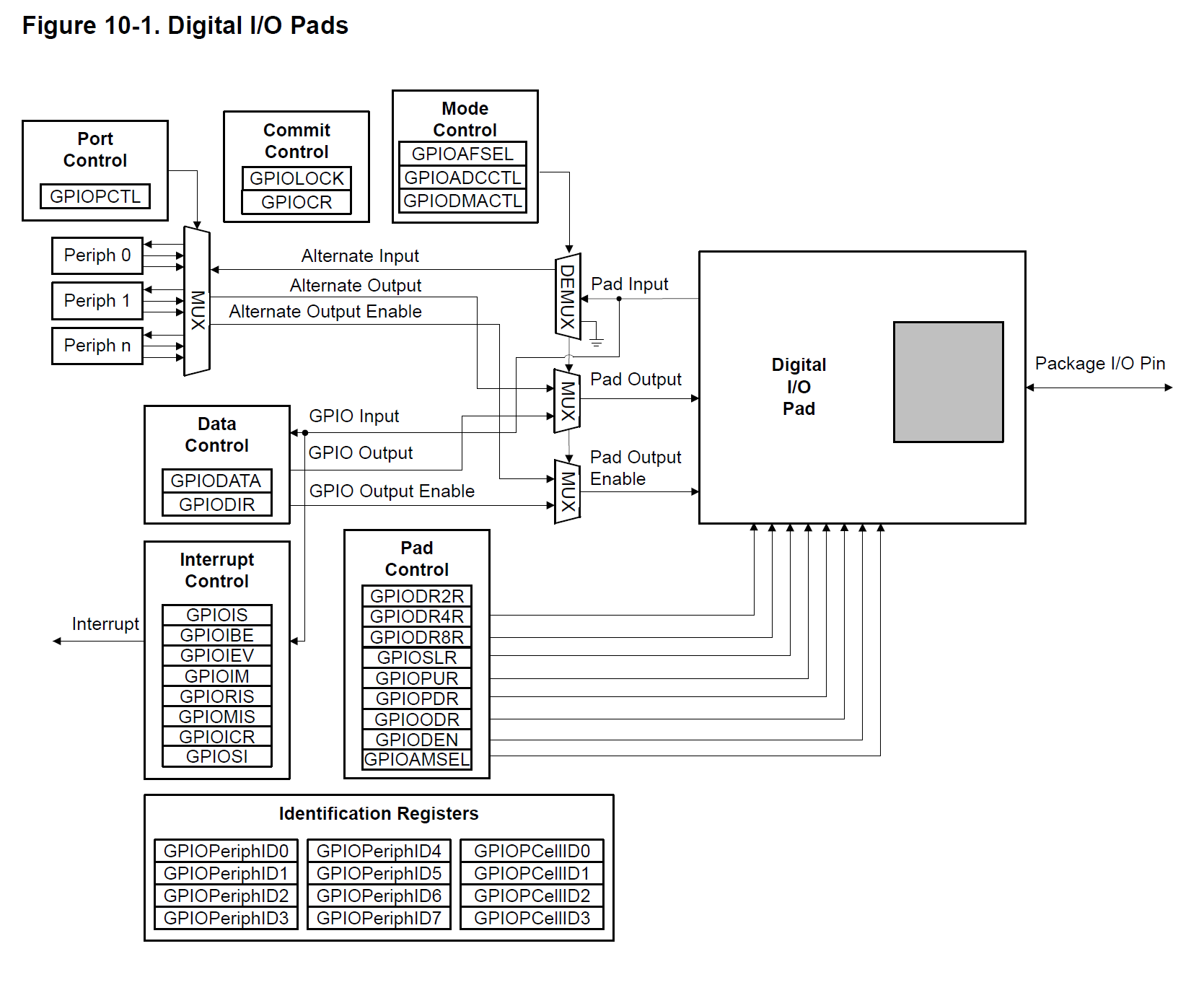
First of all, keep in mind that all of the registers we use to configure GPIO have an effect on the physical GPIO hardware blocks:

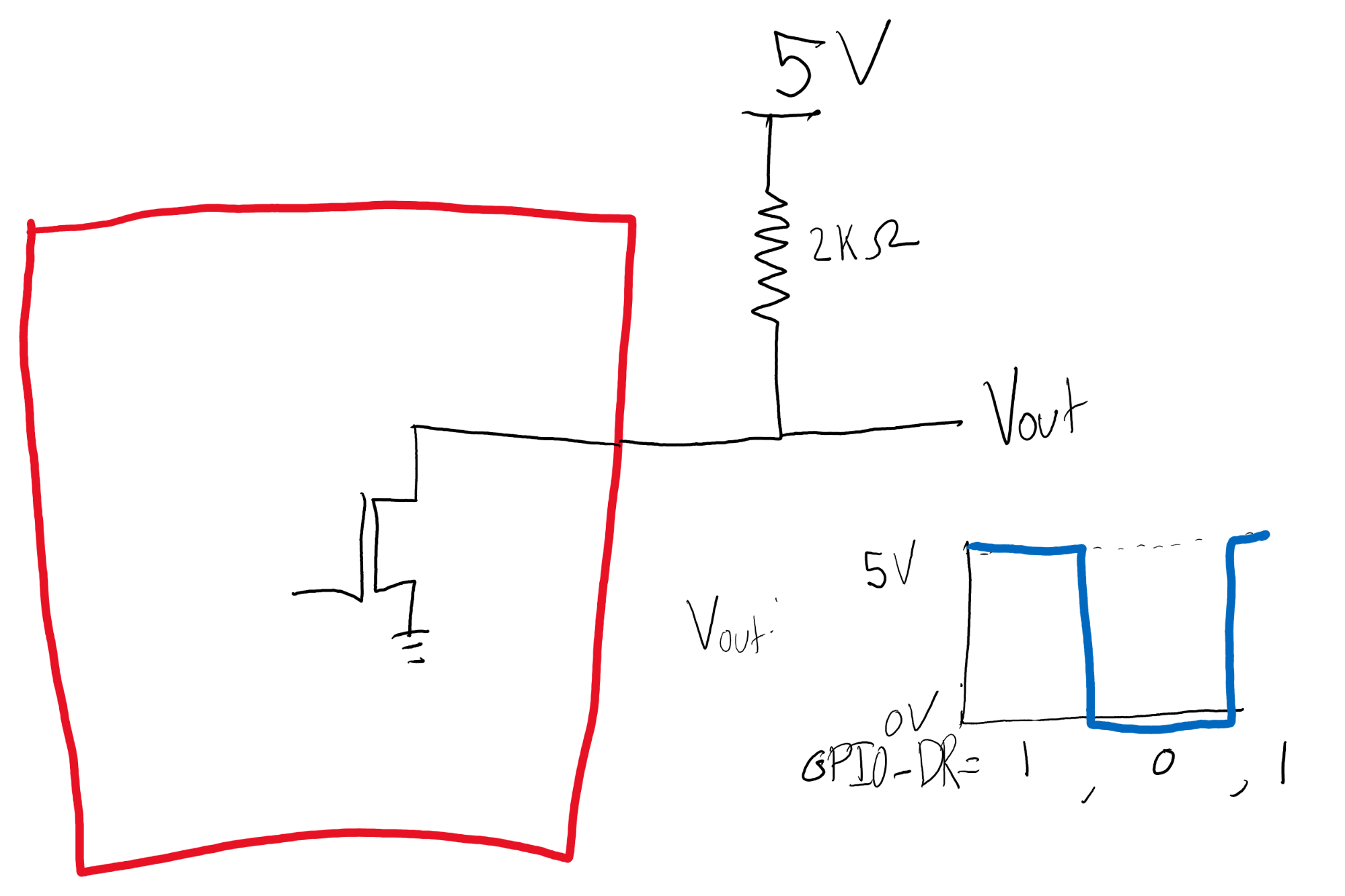
For this application, we will be utilizing the GPIOODR register, configuring the GPIO to use an Open Drain configuration. Internally, the pad is connected to the drain of a FET switch, and the source connected to ground:

Connecting an external pull-up to 5V allows us to output 5V logic:

Example Output
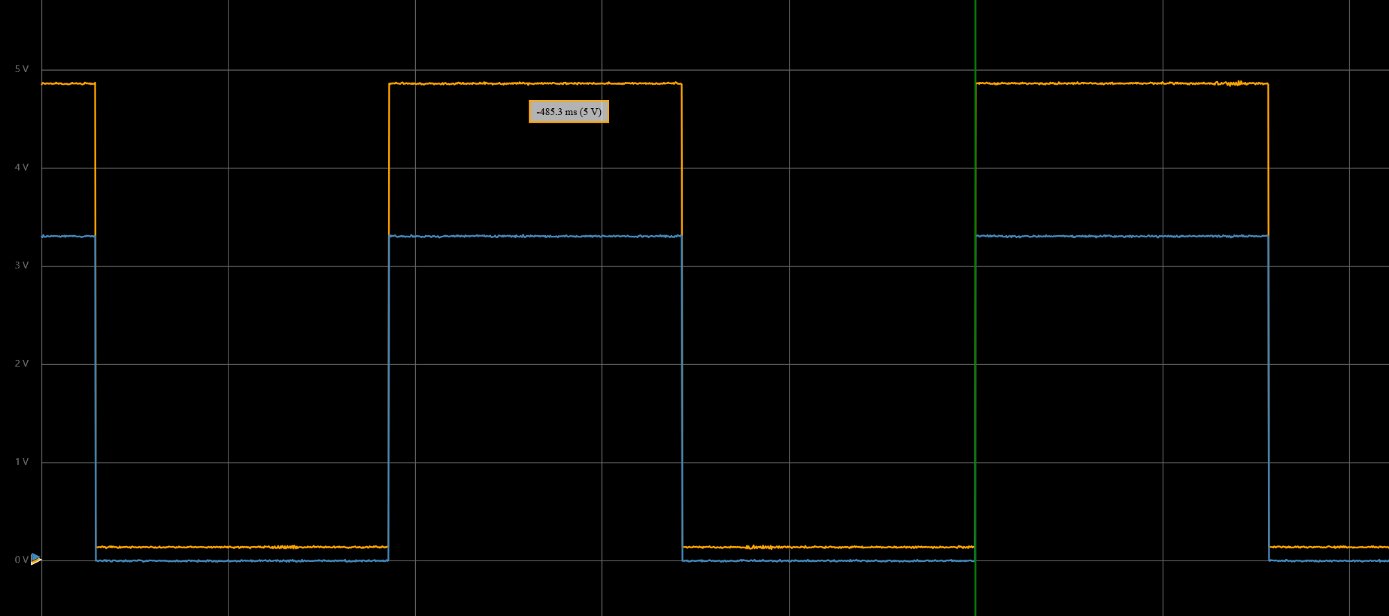
Orange channel is open drain with a 2K pull up to 5V
Blue channel is a normal 3.3V logic pin
Both are being written with the same values at the same time, so there does not appear to be logic reversal, but make sure to verify with your own setup.

Code
The code used in this class is a bit different than the TI provided TivaWare software, but register names should be fairly consistent across software interfaces. See below for example code configuring PA7 as open drain, PA6 as normal output. The two different registers are GPIO_PORTA_ODR_R and GPIO_PORTA_DR4R_R.
SYSCTL_RCGCGPIO_R |= 0x01; // 1) Port A clock
while((SYSCTL_PRGPIO_R&0x0001) == 0){};// ready?
GPIO_PORTA_AMSEL_R &= ~(3<<6); // disable analog
GPIO_PORTA_PCTL_R &= ~(3<<6); // configure as GPIO
GPIO_PORTA_DIR_R |= (3 << 6); // PA6 PA7 outputs
GPIO_PORTA_AFSEL_R &= ~(3 << 6); // normal function
GPIO_PORTA_ODR_R |= (1<<7); // PA7 Open Drain Enable
GPIO_PORTA_DR4R_R |= (1<<7); // PA7 4mA drive enable, since 5/2E3 = 2.5 mA > 2 mA default drive
GPIO_PORTA_DEN_R |= (3<<6); // Digital enable PA 6 and 7
GPIO_PORTA_DATA_R &= (3<<6);
References
1 TM4C123GH6PM https://www.ti.com/lit/ds/symlink/tm4c123gh6pm.pdf
2 Use conditions for 5-V tolerant GPIO Tiva C https://www.ti.com/lit/an/spma053/spma053.pdf